 Andy Anthony, managing director of Monitran, explains how vibration-based condition monitoring is at the heart of a ‘Virtual Engineer’ protecting a number of Stork’s filling machines in dairies around the UK
For milk-bottling plants, high-volume and high-efficiency are crucial, particularly in light of the low margins in the dairy industry. Accordingly, filling machines are required to operate at speed and, ideally, 24 hours, seven days a week.
Understandably, maintenance needs to be carefully scheduled and it is crucial to be forewarned of any failure, such as a problem arising from the unexpected wear or breaking of a machine component. Using a strategy of condition-based predictive maintenance (CBPM) can be invaluable. It allows for the better scheduling of maintenance and, if the CBPM strategy is built around real-time condition monitoring, warnings can be given about impending failures.
Stork is a keen advocate of CBPM. The company is renowned the world over for the versatility and durability of its filling machines, be they handling bottles or jars. Its Dairyfill rotary fillers are used extensively for filling fresh dairy products and when handling fresh and extended shelf life milk; which requires great care (read cleanliness).
Since 2010 Stork has been working with the Institute of Industrial Research (IIR) within the University of Portsmouth to develop an advanced condition monitoring system – dubbed the ‘Virtual Engineer’ – for its rotary fillers and for which the company received funding under the UK Government’s Knowledge Transfer Programme (KTP).
Those in the industry know that changes in vibration levels can provide early warning of a failure, and Stork has used vibration monitoring in the past on its filling machines; usually applied by the end-user or a third party maintenance company. However, the monitoring was typically performed at scheduled intervals, which can have its problems if important clues are missed between inspections.
Other issues can arise if readings are significantly different between the most recent inspection and earlier ones – because it will not be clear where the problem is on the fault curve (see panel). And making sense of the readings is another matter – i.e. complex graphs that need to be interpreted by an experienced vibration analyst that a dairy would not typically have ready access to.
Machines can of course be protected by systems which use raw vibration levels to provide a basic traffic-light warning system on site. However, such systems have to walk the thin line between being too sensitive (and giving false alarms) and not being sensitive enough (to recognise faults early enough).
Stork’s KTP-funded project, the Virtual Engineer, set out to address all of the above shortcomings and not only record the vibration signatures of its rotary fillers but also to make intelligent decisions using ‘Fuzzy Logic’ (which is close to a human’s decision-making processes) based on the clues in the data.
Data collection and analysis
Stork’s rotary fillers are complex machines, with several gearboxes and bearings, and the early challenges were to determine how many vibration sensors to employ, which types to use and where best to mount them. Here, Stork turned to Monitran, the UK-based OEM of accelerometers.
Monitran made a site visit to a large UK dairy to see a Stork filling machine in operation and, based on its observations and considerable experiences with (the monitoring of) rotating machinery, recommended the use of mechanically-mounted, stainless steel, single axis, low-profile, industrial sensors sealed to IP65 (because of the potentially wet environment) and with integral cables (as opposed to connectors) at a number of key locations.
Stork began fitting vibration sensors to its filling machines at sites in the UK. The Virtual Engineer team used National Instruments data acquisition units (which can cater for up to 16 analogue inputs) to convert the sensors’ outputs to digital (at 24-bit resolution) and used algorithms written in Microsoft C# to stream data over the internet to store data in an SQL server database.
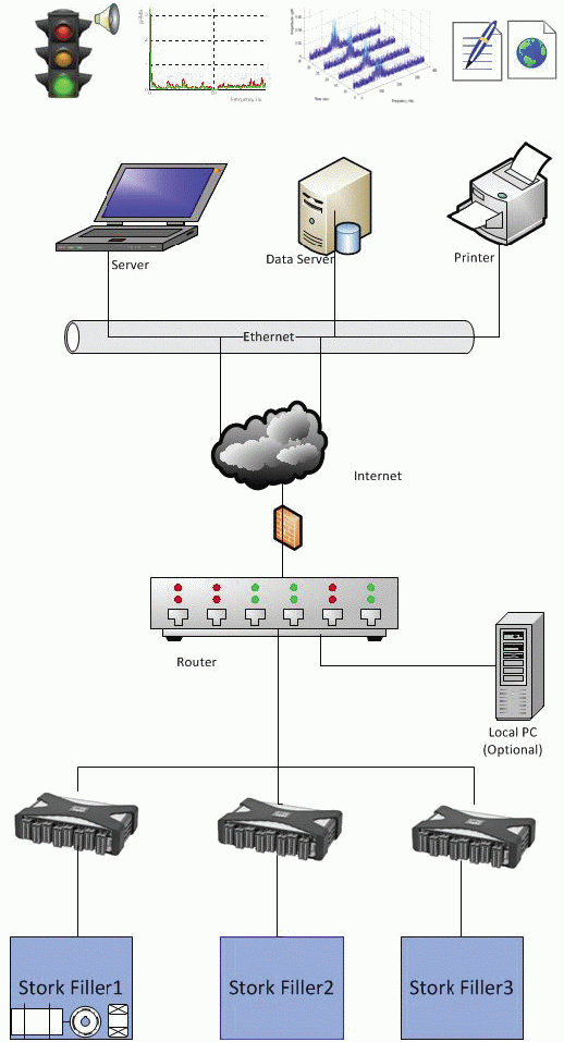
Machine learning algorithms automatically analyse data and make intelligent decisions based upon historical data. Decisions are also based on electrical current and temperature analysis of the machine. Figure 1 shows a system overview.
Data is sampled at a nominal 3kHz, which enabled the VE team to build quickly a picture of rotary filler health. With this wealth of data it was possible to recognise ‘normal’ behaviour (for different modes of operation) across the board on a machine-by-machine basis (as no two rotary fillers have exactly the same vibration signature) and then craft a number of anomaly detection algorithms; similar to how banks are able to flag radical changes to an individual’s credit card spending as a possible indication of theft or fraud.
Interestingly, the VE team’s efforts produced early results when the tell-tale signs of a gearbox failure were recognised; in a machine which was already protected by a third party complex spectrum analysis warning system but for which no alarm had been raised. Specifically, the fault was with a gear which rotates at a low speed (circa 7rpm) and the danger with any low frequency noise is that it can be easily masked by the ‘noise floor’.
By sampling at such a high speed, and performing time and frequency analysis on the data, the Virtual Engineer was able to detect the anomaly amongst the background noise; whereas the on-site protection system had its alarm levels set relatively high (i.e. high enough above the noise floor to avoid false alarms).
It is estimated that Stork saved about £15K by avoiding a catastrophic failure of the gearbox, to say nothing of the loss of production which can be as high as £20K per day depending on the size of the dairy.
Conclusion
The traditional approach has, to date, relied on threshold indicators – set to raise an alarm based on broad spectrum noise levels exceeding estimated levels – and the occasional analysis of vibration signatures which has the aforementioned flaw of you not knowing where you are on the fault curve if something is amiss.
The Virtual Engineer is something altogether new, and marks the first use of a remote, real-time, asset monitoring system within a CBPM strategy built primarily around vibration levels in a dairy application; and possibly the food and drink industry as a whole.

No longer lost in the noise
Above, the GUI developed by Stork’s Virtual Engineer team shows the vibration signature of the gearbox with the developing fault. The blue trace shows 1,000 samples recorded at 3kHz, i.e. of sufficient frequency to capture the occasional energy spike. The red trace shows the vibration energy (magnitude) in the frequency domain. Note how the spike at about 250Hz isn’t that much higher than the ‘noise floor’.
Further reading
The details of the detection of the failing gearbox mentioned in this case study can be found in the IEEE research paper entitled ‘Application of Multi-Fuzzy System for Condition Monitoring of Liquid Filling Machines’. This can be purchased from: www.ieeexplore.ieee.org/Xplore
Where on the fault curve?In the event of a significant change in vibration levels between readings you will never know where you are on the fault curve. For example, are you witnessing the gradual degradation of a component that started failing the day after the previous inspection (and which can be addressed during the next scheduled service) or are you seeing the first signs of an imminent failure (i.e. a rapid degradation for which even checking the levels again tomorrow may be too late)? In short, unless you know where you are on the fault curve you can’t, with confidence, act on the data to hand). |
Stork
T: 01895 251621
www.sfds.eu
Monitran
T: 01494 816569
www.monitran.com
The Institute of Industrial Research
University of Portsmouth
T: 07831 631672