 Die cast parts made from aluminium and magnesium alloys are increasingly being used in the automotive industry since they ensure a considerable reduction in vehicle weight. Zero-defect quality at the lowest possible cost is an essential requirement. A system from VisionTools Bildanalyse Systeme GmbH, Germany, with integrated image processing uses an Ensenso 3D stereo vision camera from IDS to record the geometry of each individual cast component. It checks the correct condition and completeness of all sprues, casting beans, runs, channels or feeders. Typical die cast parts made using these alloys are engine components, transmission housings, chassis parts and tailgate frames. Since faulty components often cause malfunctions and expensive follow-up costs, built-in inspection systems, which check every component for completeness, will ensure a consistently high quality of the parts. This system also checks that the production tool is completely emptied after removal so that it is not destroyed the next time it is filled due to residual material and the high pressing force.
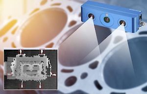
The inspection system
The robot places the component in front of the 3D camera. Depending on the size and position of the component, several images are required to check all beans, slugs and sprues. The image acquisition and evaluation takes between 0.3 and 1.2 seconds per component position. The type and test position number are specified by the machine control system. The quality of stereo vision depends directly on the lighting conditions and surface texture of the objects to be inspected and different workpieces often have different gloss properties. Ensenso 3D cameras use the “Projected Texture Stereo Vision” method. Each model uses two CMOS cameras and a projector that projects light patterns onto the cast components to be captured to increase the accuracy of the surface image. Since the distance and viewing angle of the cameras as well as the focal length of the optics are known, the Ensenso software can determine the 3D coordinates of the object point for each individual image pixel and merge them into a 3D point cloud of the component to be processed. The Flex View projection technology integrated in the N35 model further increases the accuracy of the measurement results by linearly shifting the position of the projector mask in the light beam in very small steps. This moves the projected texture on the surface of the component and creates additional structure to help with the reconstruction. Acquiring multiple image pairs with different textures of the same object scene produces a lot more image points, resulting in an increase in resolution. In addition to the resolution, the robustness of the data on difficult surfaces also increases, as the shifted pattern structures apply additional information to shiny, dark or reflective surfaces. This approach allows the beans in the images to be distinguished from the background and workpieces with different gloss properties to be reliably tested.
Versatile approach
The evaluation is carried out with VisionTools V60 image analysis software. The system can manage an unlimited number of product variants. The software ensures the implementation of type and tool changes without having to change the 3D camera. For this purpose, the software is used to define specific test characteristics for each component or test position once. These are compared with the images of the current cast component. The system issues an error message if there are variances. This eliminates the need for time-consuming retrofitting, accidental sensor adjustment or long downtimes. The system reduces part inspection errors to a minimum and the downtime of the die casting machines can be almost completely avoided, reducing costs and ensuring a smooth manufacturing process.
https://en.ids-imaging.com/casestudies-detail/en_unscathed-cast.html

