Heat installation is a highly versatile method for installing inserts into thermoplastics, with only temperature and pressure as variables. Care has to be taken to ensure that the heated insert softens but does not melt the plastic. This will avoid flash and keep the insert in place as the plastic re-solidifies.
A piloted tip should be used to guide the insert during installation and extended tips provide access to recessed holes. The insert should be installed flush with the surface, and this is usually accomplished with a positive stop.
Fixturing is simple when installing with heat – the sole purpose being positioning the hole under the installation tip. The radial stresses are minimal. This makes heat insertion ideal for thin walls or components which are difficult to fixture with the rigidity required for ultrasonic installation. Since only a low insertion pressure is used and there is no vibration, the contact area between the driver and insert is not critical, making this process ideal for symmetrical inserts with small bearing surfaces.
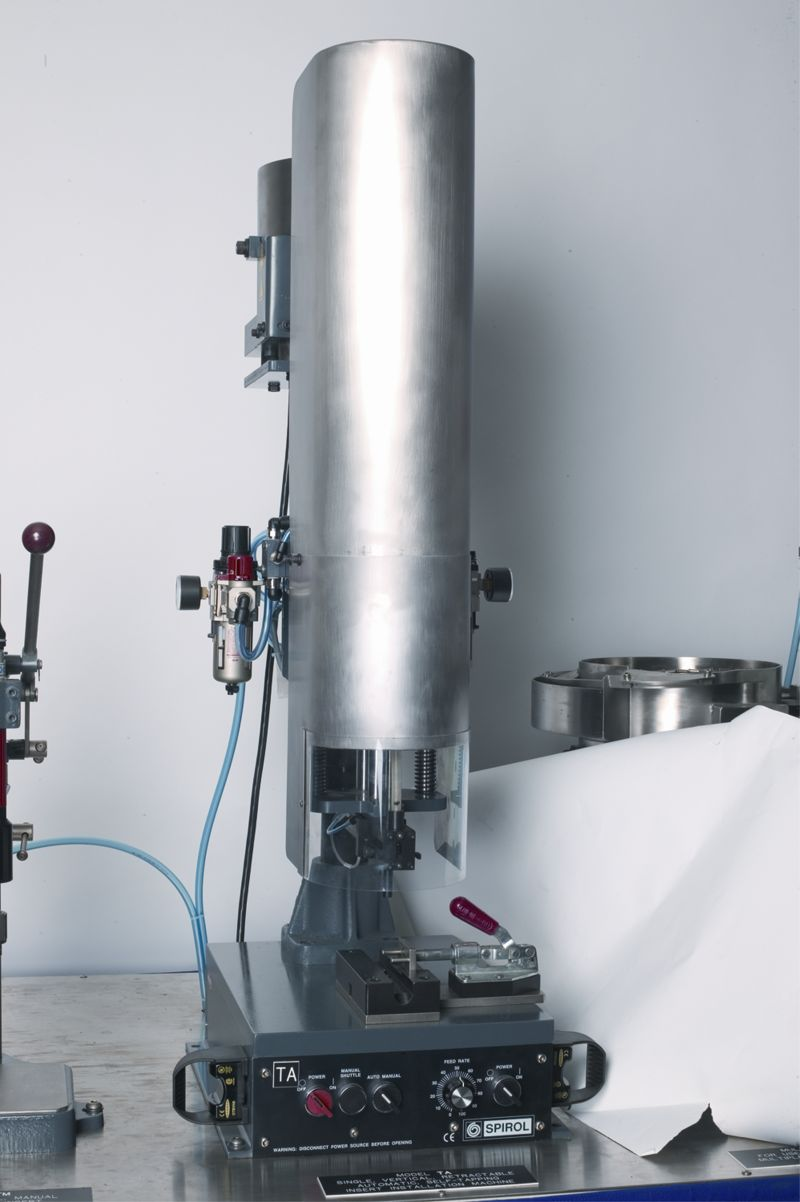
There are two methods of applying heat to the insert. Firstly, with a heat tip that transfers heat to an insert which has been manually placed into the hole. Secondly, with a pre-heat chamber which heats the insert to the appropriate temperature and the installation is with a non-heated quill. The latter method is utilized in the Spirol Model HA Automatic Heat Insert Driver. Since the insert cools during installation, this method is not suitable for plastics with a high filler content. The pressure and temperature settings for these machines are programmed into the controller and these drivers are set up for a specific insert/plastic combination.
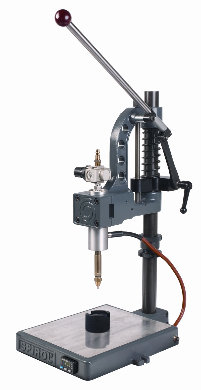
 The heated tip method is employed in the Spirol Model HP pneumatic and Model PH platen multi-tip heat insert drivers. Here, it is recommended to start with a temperature 50°F above the initial softening temperature for the plastic in question. For plastics with fillers, this initial differential should be 150°F. Pressure is insert-size dependent and should be as low as possible in the 5 to 15 PSI range. The pressure should be just enough to push the Insert into the hole as the plastic melts.
The process of determining the right temperature/pressure combination is not complex, but it takes some experimentation. It is suggested that an installed insert be sectioned through its centre line and that the insert halves then be removed from the plastic material. The plastic material should then reveal a negative image of the insert profile. This defines the correct settings and assures optimum performance.
 Press in insert installation is the easiest installation method. Place the insert pilot into the hole and use a hammer or arbor press to seat it. A piloted, extended punch can be used for recessed locations. In high volume applications, an automatic Insert Driver such as a SPIROL Model PR or Model CR can be used to feed the inserts into position and press them into place. Series 50 inserts are symmetrical, and Series 51 can be easily oriented.
When the insert is pressed into the hole, the slots allow the insert to compress into position. The insertion pressure is low and it can be easily pressed into position with the methods suitable for Press-In inserts. Once in place, the insert is expanded by the assembly screw. The screw should project from the bottom of the insert at least two threads to assure full expansion.
Ultrasonic installation is a very effective – but complex -method of installing inserts.
The effective application of this technology requires expertise to assure consistent quality. The variables are amplitude, down speed, pressure and weld time. A special hardened steel or carbide-faced horn is required to minimize wear.
 The insert is placed into the hole and the horn of the ultrasonic inserter is pressed down on the insert. The horn transmits ultrasonic vibration to the insert and the friction from the vibration of the insert melts a thin film of plastic to the metal-plastic interface. Pressure from the horn forces the insert into the hole. When the horn is removed, the melted plastic next to the insert solidifies. The inserts should be installed flush with the surface. The horn travel needs to be limited either mechanically or with switches.
Fixturing of the plastic component is very important when ultrasonically installing an insert. It has to be held rigid to get the desired vibration between the insert and the plastic. 20% of the insert area should be in contact with the plastic prior to the application of vibration and pressure. A tapered hole combined with a tapered insert facilitates a sufficient contact area. A pre-trigger switch is recommended to prevent cold pressing the insert into place. A large contact area between the horn and insert is also desirable.
The ultrasonic method is limited to thermoplastics and is particularly suitable for amorphous polymers which have a broad softening temperature range. This allows the plastic material to soften gradually, thus tolerating a wide range of pressure/amplitude combinations. Semi-crystalline polymers have a sharp, comparatively higher melting point and resolidify rapidly. This requires more energy, i.e. a higher amplitude, and special consideration to the variable settings.
As a general guideline, the preferred parameter for the ultrasonic Insert installation process can be summarized as:
- Low to medium amplitude
- Low to medium pressure
- Pre-trigger
- Slow-down speed
- Minimum weld time
- Hardened horn
- Rigid fixturing
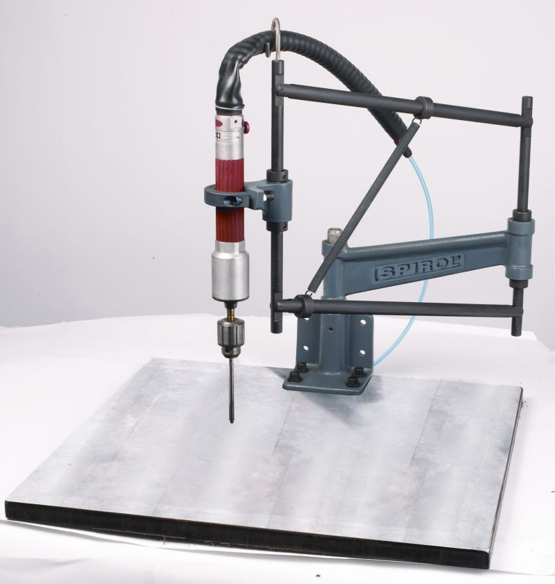
With self-tapping insert installation, since the insert is driven by its internal thread, a different driving stud is required for each insert size. For applications in recessed areas or close to walls, an extension driver is the solution. The insert is threaded on to the driver by hand and the manual press is brought down to line the insert up with the hole. The plastic component should be located against a stop to prevent rotation during installation, or fixtured to prevent rotation as well as to ensure consistent alignment of the hole. After the insert is seated, releasing the pressure automatically reverses and raises the driver.
The depth of installation is controlled by a stop on the manual press such as the SPIROL Model TM Manual Self-Tapping Insert Driver. The insert should always be installed flush or slightly below the surface.
If multiple insert locations are required, a Radial Arm Driver can be used. It is important that whatever is used provides rigidity to assure straight axial insertion of the insert into the hole.
For more information, visit www.spirol.com or contact Spirol Industries Ltd, Princewood Road, Corby, Northants, NN17 4ET, Tel: +44 (0) 1536 444800, Fax: +44 (0) 1536 203415, email: uksales@spirol.com