 The Vision sensor detects the object, the robot picks it up – this teamwork only functions in practice if sensor images have first been converted into robot coordinates. The latest Vision sensors are now equipped with a calibration function that enables the configuration of coordinate conversion in just a few mouse clicks.
Handling robots and vision sensors evolve in two very different worlds: the origin (0.0) of sensor coordinates is usually the top left-hand corner of the image and length measurements are output in image pixels. The robot, on the other hand, needs all data in millimetres in relation to a place in the real world, e.g. its base. Until now, the necessary conversion of coordinates involved considerable programming work in the robot control system. Not only were calculations required for the part position, but factors such as perspective distortion caused by the sensor’s diagonal angle of view and pincushion distortions of the sensor lens also had to be taken into account.
 Calibration instead of programming
Vision sensors from SensoPart’s VISOR® series considerably facilitate set-up work, for example in a typical pick & place application for an automotive supplier in the south of Germany (fig. 1). The otherwise manually created routines are already pre-configured in the sensor in the form of a calibration function and need only be adapted to the specific application – similar to the ‘teach-in’ procedure with a switching sensor. This requires the creation of a so-called point pair list of image and world coordinates with at least six corresponding pairs of points. The robot places a suitable calibration part in various 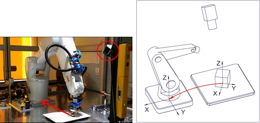 positions in the Vision sensor’s field of view and the respective coordinates are transmitted from the robot control system to the sensor configuration software. It is a simple as that – time-consuming intervention in the software control system is no longer necessary.
Simple set-up and adjustment
 Once calibrated, the sensor transmits each part position in absolute robot coordinates so that the robot can grip the part directly without further calculations. Possible perspective and lens distortions are also automatically corrected in the process. The calibration procedure described above can also be automated through interface commands, e.g. via Ethernet.
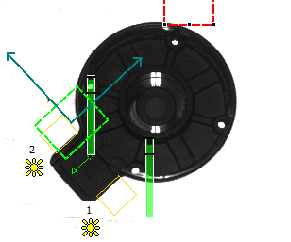
Calibration can be easily adjusted to changing part shapes. A vertical offset between the calibration and measurement plane can be taken into account and gripper correction, e.g. for parts with a side handle (fig. 2) is also possible. Available space around the part to be gripped is also checked; parts on top of one another or too close together are not even signalled to the robot. Thanks to these versatile configuration options, the VISOR® calibration function covers all the eventualities of a pick & place application, boosting efficiency both during the initial set-up and in the case of modifications.


